
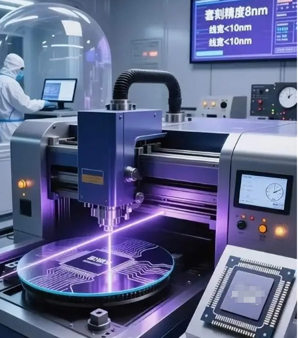
On the fab floor, a heater isn’t just warming a chamber. It sets the thermal baseline for photoresist soft bake and hard bake, for wafer cleaning and drying, and for every step where temperature drift shows up as overlay error and CD bias. When the power cable feeding that heater misses on performance, you don’t get a polite alert. You get drift. You get particle spikes. You get unplanned downtime. A fab heater power cable isn’t a commodity. It’s the last link in the thermal control loop, and it has to carry current without adding electrical noise, without turning into an intermittent connection, and without outgassing or shedding particles in a Class 1–100 cleanroom. In lithography and photoresist processing, ±0.1°C matters. A loose termination, a jacket that cracks under thermal cycling, or a conductor that heats under load will nudge the entire bake profile.
What matters, technically
We built this power cable for fab heaters to meet the same expectations that drive semiconductor equipment specs, and we validated it against the acceptance criteria used on installed tools. The choices are direct answers to what the process actually demands. **Conductor and current handling.**The conductor geometry is sized to keep voltage drop low over the run length, because voltage drop at the heater becomes temperature error. Typical heater loads need stable delivery with minimal resistive heating in the cable itself. We spec stranded conductors that are flexible enough for repeated tool moves and maintenance, while keeping the current rating high enough to hold cable temperature rise within safe margins. **Insulation and jacket for heat and chemicals.**Fab heaters live in hot zones. The insulation has to sit at bake-like temperatures day after day without hardening, cracking, or going brittle. We use high-temperature-rated materials that resist thermal aging, and a jacket chosen to stand up to common cleaning chemistries and solvents. Outgassing and micro-cracking aren’t theoretical—they’re exactly how particle counts climb. **Shielding and EMI discipline.**Noise in a fab doesn’t stay neatly contained. A heater power cable needs shielding so it doesn’t inject noise into nearby sensors, RF sources, and control lines. Clean grounding and continuous shield integrity keep electromagnetic interference from upsetting temperature control loops when the bake is critical. **Connector interface and termination reliability.**More failures happen at the termination than in the middle of the cable. We match the connector styles you see on fab heaters and semiconductor equipment—secure, keyed, and serviceable within tool constraints. Terminations are engineered for mechanical stability and low contact resistance. The point is repeatability: the same thermal profile today, tomorrow, and after maintenance. **Cleanroom behavior: particle control and clean compatibility.**The cable can’t become a particle generator. We choose materials and construction methods that keep particle generation down, and we design surfaces that are cleanable and compatible with cleanroom practice. In real life, that means the cable doesn’t shed when flexed, and preventive maintenance doesn’t introduce a contamination source. **Mechanical durability in real tool motion.**Heaters get moved, adjusted, and serviced. Cables see bending, torsion, and contact with tool fixtures. We reinforce the cable with strain relief that pushes mechanical stress away from the terminations, because that’s where intermittent opens start.
Why this works in production
In semiconductor manufacturing, the heater is part of the recipe. If the heater underperforms, soft bake and hard bake lose repeatability. You see it in film thickness variation, sidewall profile drift, and yield loss that’s expensive to chase. This power cable keeps the heater supplied cleanly so the thermal control loop can do its job. The payoff is predictable temperature uniformity across the wafer and bake profiles that repeat lot after lot. When the thermal profile stays stable, you cut rework, reduce scrap, and keep the line moving. It also cuts unplanned interruptions. A robust termination and a jacket that survives thermal cycling mean fewer emergency calls for loose connections, cracked insulation, or temperature readings that drift. In a high-throughput fab, preventing one unscheduled stop can pay for the cable several times over. Energy use isn’t an afterthought. Lower voltage drop and lower losses mean the heater control doesn’t have to overcompensate. That translates into lower energy draw over time, without changing the process intent. And because the cable is built for cleanroom constraints, it doesn’t fight contamination control. Particle generation stays low, outgassing is controlled, and maintenance doesn’t leave behind a hidden contamination source that shows up weeks later as a yield excursion.
The practical details you need
No cable fits everything. Matching this power cable to your heater comes down to three real-world constraints. Confirm the electrical interface: voltage, current, connector type, and polarity. A mismatch at the connector isn’t a minor inconvenience—it’s a reliability and safety issue. Confirm the thermal environment. If the cable runs through a high-temperature zone, the insulation and jacket rating have to match it. We can supply variants for different thermal budgets, but the application data has to be accurate. Plan the routing. Even with strain relief, sharp bends and constant rubbing against metal edges will win eventually. Use proper cable guides and respect bend radii. Treat the cable as part of the tool, not an afterthought. If you’re replacing an existing cable, the fastest route is to share the tool model and the existing cable part number. We can align the equivalent spec so the cable meets the same performance envelope without forcing you to re-engineer maintenance procedures. When uptime and repeatability define your output, the power cable isn’t incidental. It’s one of those details that keeps the thermal process honest.